Prototype experiments for the polarized ILC positron source
Prototype experiment for the undulator-based scheme: E166 at SLAC
Layout and goals:
 The
experiment E166
was approved in 2003 and had two runs of data in 2005 at the FFTB at SLAC
with about 8.5 millions events on tape.
The
experiment E166
was approved in 2003 and had two runs of data in 2005 at the FFTB at SLAC
with about 8.5 millions events on tape.
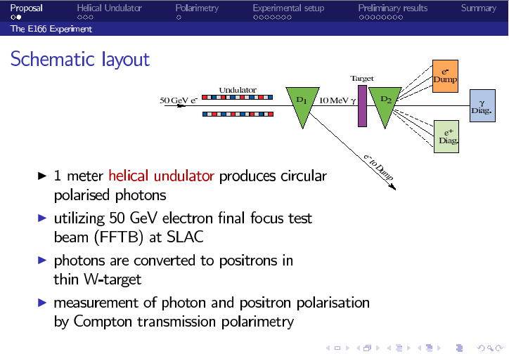
Its goal was to demonstrate the production of polarized positrons with an helical undulator.
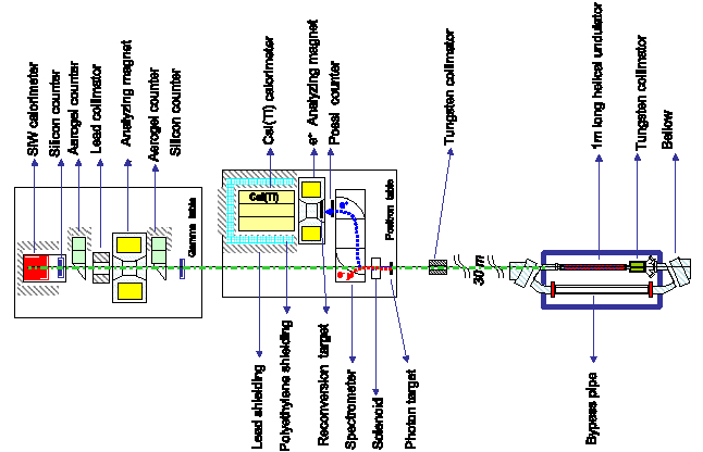
It uses an 1 m helical undulator in connection with the 50 GeV FFTB.
Photon and positron diagnostics
has been done. More details are given in
this talk,
summarized on this poster contribution
to EPAC'06.
|
Results:
 The
experiment
run at an electron energy of 46.6 GeV, the undulator
period was 2.4 mm (undulator K-factor~0.19), which leads to the energy of the first harmonic of
the undulator radiation of about 8 MeV. The photons were converted at
a thin tungsten target with 0.25 radiation length, leading to polarized
positrons with a maximal energy of also about 8 MeV --
in agreement with theoretical predictions and simulation.
The
experiment
run at an electron energy of 46.6 GeV, the undulator
period was 2.4 mm (undulator K-factor~0.19), which leads to the energy of the first harmonic of
the undulator radiation of about 8 MeV. The photons were converted at
a thin tungsten target with 0.25 radiation length, leading to polarized
positrons with a maximal energy of also about 8 MeV --
in agreement with theoretical predictions and simulation.
The incoming 10^10 electrons per bunch were leading to about 10^9 photons per bunch.
The conversion into positrons at
the W target is about 1%
in that photon energy range of about 10 MeV.
|
 The photon and positron
diagnostics was done wit the Compton transmission method, best
suitable in that energy region.
This method is based on the spin dependent Compton scattering of polarized photons with
polarized target electrons in a magnetized iron. Flipping the iron magnetization leads to an asymmetry in
the observed transmitted photon rate.
The photon and positron
diagnostics was done wit the Compton transmission method, best
suitable in that energy region.
This method is based on the spin dependent Compton scattering of polarized photons with
polarized target electrons in a magnetized iron. Flipping the iron magnetization leads to an asymmetry in
the observed transmitted photon rate.
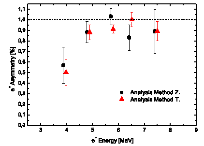
Both photon and positron asymmetries have been analyzed for different energies.
Two independent and different approaches
(methods `T' and `Z') for the data analysis have been used and show
consistent results:
The photon (positron) asymmetry is in the expected range of about 3.4% (0.5% - 1%).
To derive the polarization from the measured asymmetry,
the analyzing power has to be determined.
Preliminary results
give a positron polarization between 50%-90%, depending on the different energies. Final results are under work.
|
.
Prototypes for an ILC helical undulator: designs at AsteC, Daresbury and RAL, Oxford
Goals:
|
The goal of the UK heLiCal collaboration is the development of an helical undulator design for the ILC.
This work will be accomplished in collaboration with the Cornell University.
Prototypes for such a design are
short-period devices with a very short aperture and are already under construction at the AsteC, Daresbury
Laboratory and the Ruthford Appleton Laboratory at Oxford. A status report of the ongoing work can
be read in this article in the
EPAC06 proceedings.
|
Results:
An earlier iteration of the undulator BCD design (before November 2005) aimed at generating 20 MeV photons
in an undulator with a 14 mm period and a peak field of 0.8 T from a 250 GeV drive beam.
Two prototypes for these parameters have been designed, one using superconducting magnets and one using
permanent magnets.
For the
superconducting prototype (with twenty 14-mm periods)
the on-axis magnetic flux were measured at room and at superconducting temperatures.
|
The superconducting prototype
reached 225 A (the maximum current) without quenching and the radial field was shown to reach the
nominal on-axis value of 0.8 T.
More details can be read in the
PAC05 proceedings.
|
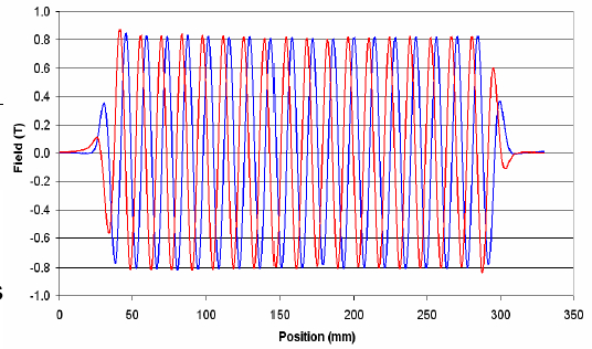
 It is also important to know how well the magnetic field in the undulator has to be controlled,
how sensitive the electron trajectory is on such field deviations and whether corrector magnets will be needed.
It is also important to know how well the magnetic field in the undulator has to be controlled,
how sensitive the electron trajectory is on such field deviations and whether corrector magnets will be needed.
Studies have shown that the magnetic field does not vary significantly up to
500 microns off-axis.
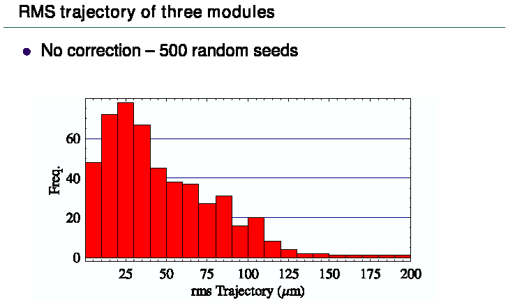
500 simulations of electron trajectories through 12 m of the undulator (3 modules) with random errors
of about 5% in the peaks (i.e.
errors assumed to be about 3-5 times worse than in the measured device) have been made.
The
results derived without applying any corrector magnets, show that the average rms electron trajectory is
less than 50 microns,
which is far below the before mentioned 500 micron range.
Given the size of the rms trajectory with realistic errors the electron orbit through the undulator is not
a crucial issue. No corrector magnets are absolutely needed. More details are given in
this talk.<\a>
|
The
permanent magnet undulator prototype
(with ten 14-mm periods), the
Halbach undulator, was built from NbFeB magnets.
Initial field measurements have confirmed that the on-axis field is helical.
|
Based on operational considerations, however, the decision was taken by the collaboration
to focus on superconducting magnet technology for the future design work: the main argument was the ease
with which the superconducting undulator parameters could be adjusted simply by varying the
current; see more details in these
ICHEP05 proceedings
and a summary of both prototypes and the magnetic measurements
in the publication.
Current ILC undulator design:
The current helical undulator of the BCD, however, is now foreseen with these
parameters,
generating photons with an energy of 10 MeV from a drive beam with only 150 GeV;
the circular aperture has to be very narrow, 5.8 mm diameter.
These parameters are demanding.
|
To meet the requirements in change in the photon energy specification and the drive beam energy,
an extensive amount of magnetic modelling had to be carried out to reoptimise the undulator parameters.
A key result from the earlier superconducting magnet modelling was that the inclusion of an iron former
increased the on-axis field by ~0.5 T. Since the field gradient at the iron-conductor interface is very steep,
it is difficult to estimate the peak field in the superconductor.
|
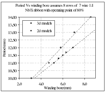
In order to scan of the undulator parameter space and study the effects of changing the period,
bore and winding size, computer modelling studies have been applied.
Current computer modelling indicates that an undulator (1:1 ratio of
copper to NbTi) with
11.5 mm period,
6.3 mm winding bore, 80 % of the critical current and 10 MeV photons at the first harmonic can be achieved.
These results are being experimentally verified with short test pieces;
more details about the magnetic modelling studies, see these
EPAC06 proceedings.
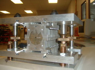
In parallel with the magnetic modelling a number of
short undulator prototypes (EPAC06 proceedings)
have been/will be built to develop fabrication techniques for the full scale modules.
|
Careful studies have also been made to study the impact of the narrow aperture, vacuum vessel
on the electron beam to ensure that wall impedance or surface roughness do not degrade the electron beam
properties.
Resistive wall wakefield
and surface roughness
studies
have shown that there is a small effect on the electron
beam energy spread. The beam energy spread would increase
by about 10% for stainless steel, but only by about 1 % for an Al, Cu or Au coated vessel.
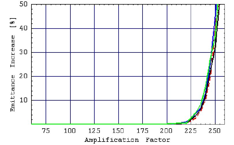
Studies on the
emittance dilution
due to the resitive wall wakefields indicate that
the strength of the kick along 200 m of undulator would need to be amplified by a factor greater than 200
to have any noticeable effect, more details se in
this talk.
To mitigate any further wakefield effects a smooth copper pipe (r~30 nm) with a 6.3 mm outer diameter and
5.8 mm inner diameter will be used, which is available from industry today.
It will be important to achieve and maintain a vacuum in the undulator vessel.
Studies on the electron cloud instability have shown that for a
vacuum of 100 nTorr
the increase in beam amplitude is about 0.2%. By installing
photon collimators at about every 10-20 m, for instance between every undulator cell,
a suitable vacuum can readily be maintained. Further details and
a summary can be found in this
EPAC06 proceedings.
|
Undulator-based source studies at Cornell
Liquid metal studies
Collimator studies
Undulator studies
Alternative layouts
Prototype experiment for the laser-Compton-based scheme: ATF at KEK
Layout and goals:
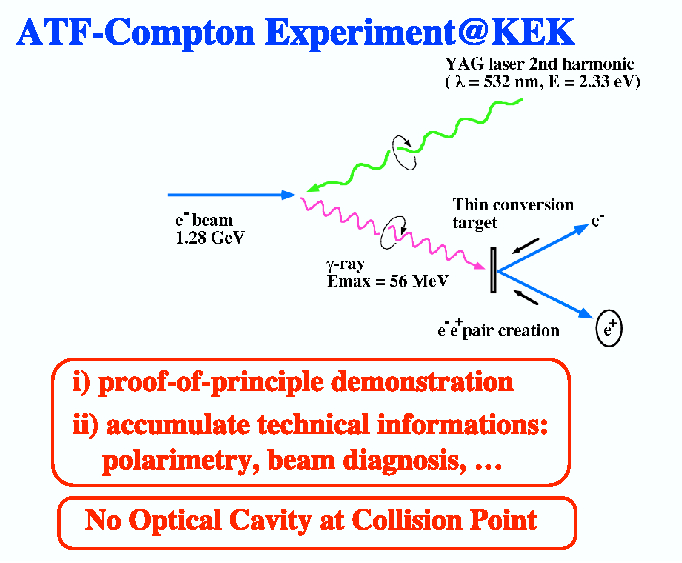 The ATF-Compton experiment at KEK
presents the `proof-of-principle-experiment'
for the laser-Compton based scheme to produce polarized positrons.
The ATF-Compton experiment at KEK
presents the `proof-of-principle-experiment'
for the laser-Compton based scheme to produce polarized positrons.
It uses the 1.28 GeV low-emittance electron beam from ATF and brings it into head-on collisions in
the Compton chamber
with a NdYAG laser (2nd harmonic light at 532 nm).
The produced photons are circularly polarized, have an energy of maximal 56 MeV and are converted at a thin W target
into polarized electrons and positrons.
More details are given in
this
talk.
|
Results:
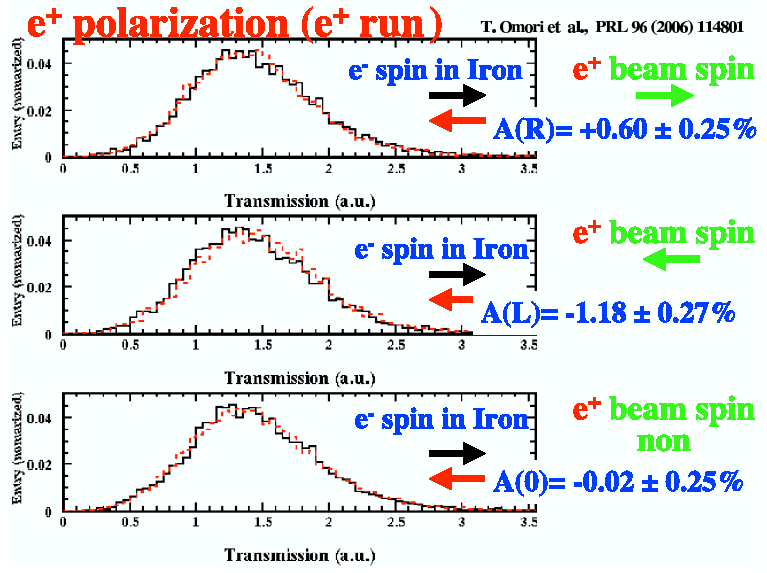 Both
photon and
positron
asymmetries have been measured via transmission
polarimetry, see explained in the box above.
Both
photon and
positron
asymmetries have been measured via transmission
polarimetry, see explained in the box above.
The measurements were done for left- and righ-polarized laser light. Changing the laser polarization
flips the positron polarization. Furthermore the asymmetry was also measured for linear laser polarization, which should
correspond to zero longitudinal polarization of the positrons.
All measurements
were perfectly consistent with the theoretical expectations.
|
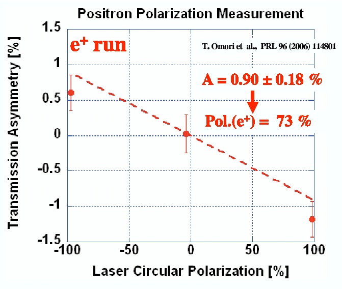 In order to derive the polarization from the measured asymmetries a
straight line was fitted to the data,
constrained by passing through the origin. The absolute value of the slope obtained to be 0.90 +- 0.18%.
The slope corresponds to the positron asymmetry assuming
100% laser polarization.
In order to derive the polarization from the measured asymmetries a
straight line was fitted to the data,
constrained by passing through the origin. The absolute value of the slope obtained to be 0.90 +- 0.18%.
The slope corresponds to the positron asymmetry assuming
100% laser polarization.
From this asymmetry, the magnitude of positron polarization was calculated to be 73% +- 15% (stat. error) +- 19%
(syst. error due to Monte-Carlo simulation).
The measurement was also done for electron polarization. All results, those for positron polarization and
those for electron polarization, are in agreement with each other.
|
|
The incoming 10^10 electrons per bunch were leading to about 10^7 photons per bunch.
The conversion into positrons at the
1mm-thick W target is about 2%
in that photon energy range of ~56 MeV. Only high-energy positrons of about 10^4 positrons per bunch
were extracted.
The momentum of the positrons was not measured, but the average energy of the positrons is, according
to the simulation, at about 36 MeV with a r.m.s. width of 8 MeV.
More details about the ATF-Compton experiment
are given in this publication.
|
Further plans: optical cavity at collision point

Next step in the R&D program for a laser-based ILC source is to enhance the photon yield.
To achieve such a goal it is
needed to
* develop
pulsed lasers
with a high multiplication factor
* get smaller waist size of the laser
* achieve smaller crossing angles at the Compton IP
|
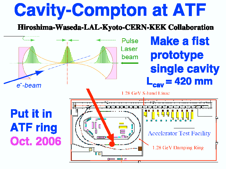
An experiment with a prototype of such a single stacking cavity is planned for 2006. The following
parameters are foreseen for this
experiment at
KEK-ATF.
More information about the R&D status of the optical cavities for the ILC and the planned prototype experiment
of the Cavity-Compton Collaboration are given in
this talk.
|
Gudi Moortgat-Pick
Last modified: 25-August-2006