CLOSED ORBIT CORRECTION AND ORBIT STABILISATION
introduction
PETRA III is a new light source being reconstructed out of the existing storage ring PETRA II running at beam energy of 6 GeV with 100mA stored current. The conversion of this 2.304km PETRA II storage ring will include the total rebuilding of one eighth of the storage ring to provide space for nine straight sections to install insertion devices. The new light source with a horizontal beam emittance of 1nm.rad and a 1% emittance ratio, needs careful magnet alignments, orbit stabilization and closed orbit corrections. Side by side the small vertical emittance imposes tight tolerances on the vertical dispersion that is created by the misalignment of the sextupoles. The closed orbit results from field errors arising from magnetic element positioning errors. The most severe effects come from misalignment of quadrupole magnets, where the resulting dipole field is proportional to both gradient and alignment error. The closed orbit distortion has been estimated with the alignment tolerances and field errors presented in Table-1. Since the integrated quadrupoles strength in the new octant is two to three times higher than in the old octants the alignment requirements are accordingly tighter. The closed orbit has been simulated for 600 different sets of alignment errors and field errors assuming a Gaussian distribution (truncated at 2s) with RMS values given in Table-1. The closed orbit is obtained using the MAD.x program in the presence of damping wigglers and synchrotron radiation. The expected RMS values for the closed orbit in the horizontal and vertical plane are 7mm and 4mm respectively as shown in the Figure 1.
Figure 1: The horizontal and vertical RMS COD produced by 600 sets of random errors before correction.
Table-1: Magnet, BPM alignment & magnet field errors.
|
|
No. of magnets |
Dx |
Dy |
Ds |
Dy |
Field Errors |
|
[mm] |
[mrad] |
|||||
|
Dipoles |
214 |
0.25 |
0.25 |
0.50 |
0.20 |
|
|
Quadrupoles Old Octant |
281 |
0.25 |
0.25 |
0.50 |
0.20 |
|
|
Quadrupoles New Octant |
98 |
0.10 |
0.10 |
0.50 |
0.20 |
|
|
Sextupoles |
140 |
0.25 |
0.25 |
0.50 |
0.30 |
|
|
Monitors |
203 |
0.2 |
0.2 |
|
|
|
Closed Orbit and Dispersion Correction
The closed orbit will be measured by 209 beam position monitors (BPM). In the old octants the BPMs are located next to each horizontal defocusing quadrupoles. Extra windings on 123 dipoles and 59 independent magnets are used as horizontal correctors while 189 independent magnets are used as vertical correctors. Details of BPMs, horizontal and vertical correctors in DBA cell in the new octant are shown in Figure 2.

Figurer 2: BPMs
and correctors distribution per DBA cell, ![]() symbolising BPMs,
symbolising BPMs,
![]() [slow] &
[slow] &![]() [fast]
horizontal correctors,
[fast]
horizontal correctors, ![]() [slow] &
[slow] & ![]() [fast] vertical
correctors.
[fast] vertical
correctors.
For PETRA III straight forward orbit correction is not sufficient, dispersion correction has to be included in transverse planes. The small vertical emittance imposes tight tolerances on the vertical dispersion. In addition the horizontal dispersion function in the wiggler and undulator sections has to be controlled. An algorithm for the simultaneous optimization of the closed orbit and the dispersion in the transverse planes is applied. This algorithm is given by the following system of linear equations:
 [1]
[1]
With ![]() being
the closed orbit and
being
the closed orbit and ![]() the
dispersion measured at the BPMs, R the orbit response
matrix, S the dispersion response matrix and
the
dispersion measured at the BPMs, R the orbit response
matrix, S the dispersion response matrix and ![]() corrector
kicks. a is a weighting factor used to shift from a pure orbit
(a=1) to a pure dispersion correction (a=0). Singular Value Decomposition (SVD) has been
proven to be a numerically robust method to solve such an equation. Closed orbit and dispersion correction has been
simulated to verify that the desired vertical and horizontal emittance can be
achieved. Distributions of RMS values of the orbits and vertical dispersion after
correction for 600 random seeds are shown in Figure 3(a-c). The simulations
have shown that the RMS vertical dispersion can be kept below 5.0mm in the
whole ring. The maximum corrector strength needed is below 0.5mrad. The
required resolution of the corrector power supplies has to be at least 16 bit.
corrector
kicks. a is a weighting factor used to shift from a pure orbit
(a=1) to a pure dispersion correction (a=0). Singular Value Decomposition (SVD) has been
proven to be a numerically robust method to solve such an equation. Closed orbit and dispersion correction has been
simulated to verify that the desired vertical and horizontal emittance can be
achieved. Distributions of RMS values of the orbits and vertical dispersion after
correction for 600 random seeds are shown in Figure 3(a-c). The simulations
have shown that the RMS vertical dispersion can be kept below 5.0mm in the
whole ring. The maximum corrector strength needed is below 0.5mrad. The
required resolution of the corrector power supplies has to be at least 16 bit.
Although the described correction scheme fulfils the dispersion requirements additional skew quadrupoles are foreseen to independently minimize the betatron coupling and locally correct the dispersion coupling generated in the sextupoles. For more details on spurious vertical dispersion correction, click here.
Figure 3:(a, b) the horizontal and vertical RMS COD produced by 600 sets of random errors after correction and (c) the spurious vertical dispersion.
Beam Stability
Beam stability is one of the most important requirements in synchrotron light sources. In the previous section it was shown that the design goal for the horizontal emittance and the small value for the emittance coupling can be achieved under realistic conditions. The result of the correction procedure is the so-called golden orbit; unfortunately it is not stable. Changes of the orbit may be the results of complex phenomena for example natural and cultural ground vibrations, tunnel drifts, resonant amplifications due to support, thermal deformations etc. These changes can be divided into fast and slow motion. Fast motion (f> a few tenth of Hz) has to be corrected by a feedback system. Slow motion (f< a few tenth of Hz) must be corrected by repeated standard orbit correction. Beam stability requirements are typically 10% of the beam size at the insertion devices. In the case of PETRA III the beam sizes and the divergences in the middle of the insertion sections are shown in Table 2:
According to the above mentioned demands an orbit stability of microns in the horizontal and half a micron in the vertical plane have to be achieved. It has been demonstrated at several laboratories that the required stability can be achieved viz. (ELETTRA < 0.2µm, SLS < 0.5µm, ESRF » 0.6µm. In order to estimate the parameters of the fast feedback for PETRA III, measurements have been performed to identify sources of orbit disturbances like ground motion and vibrations. In addition we measured the orbit distortions in PETRA II in a frequency range from 0.1 Hz to 500 Hz. Since a considerable part of the PETRA III magnetic structure is same as the structure of PETRA II, these measurements are useful and relevant in order to estimate orbit distortions for PETRA III.
Recently some ground motion measurements also have been taken and compared with the situation at other laboratories. The results of these measurements are shown in Figure 4(a). The power spectrum shows the typical form. From 0.1 Hz to a few Hertz the power density is a strongly decreasing function. The ground motion is mainly given by ground waves. The increase around a few Hertz is due to cultural noise. From this figure one can conclude that the situation at DESY and the ESRF are comparable.
Figure.4(b) shows the integrated spectrum which indicates that the most significant contributions to ground displacement come from frequencies below 10 Hz. The RMS value of the ground motion is below 140 nm. This noise spectrum is translated by the magnet supports and the beam optics into orbit distortions. These orbit distortions have been measured at PETRA II and results are shown in Fig.5. Comparing the two power spectra (ground motion and orbit) indicates that the orbit is basically determined by the amplification factors of the optics between 0.1 and 10 Hz and that the noise power spectrum is amplified around 20 Hz. This is due to the resonant behaviour of the magnet supports in particular the quadrupole stands. The lowest resonance frequency of the quadrupole supports is around 20 Hz.
Table-2: Beam sizes at the centre of insertion devices.
|
Device |
sx(mm) |
sx¢(mrad) |
sy(mm) |
sy¢(mrad) |
|
5m U |
34.6 |
28.9 |
6.3 |
1.6 |
|
5m U |
141.5 |
7.1 |
4.9 |
2.1 |
|
20m U |
126.6 |
7.9 |
9.9 |
1.0 |
The actual amplitudes of ground motion in the horizontal plane always stay below the limit. In the vertical plane the limit given in the picture is close to the values shown in the power density plot (Figure 4). One has, however, to keep in mind that the ground motion driven above a few Hertz is not determined by coherent ground waves but mainly by cultural noise. Summarizing the above findings the orbit distortions for PETRA III will be basically determined by cultural noise. The amplitude of the orbit perturbations will be close to the ones measured for PETRA II. So we expect that the position errors at the insertion devices is around 10 µm in the horizontal and around 3 µm in the vertical plane (see Figure 5). Therefore a fast orbit feedback is necessary. According to the integrated power spectrum of the orbit perturbations (Figure 5) this system has to fight distortions with frequency components between a few tenth of a Hertz up to approximately 100 Hz. The orbit distortion has to be reduced by a factor less than 10. Such feedback requirements have been proven to be feasible.
Figure 4:(a) The power spectral density of the ground motion at different accelerator sites and (b) the integrated power spectral density of the ground motion in the PETRA tunnel.
![]()
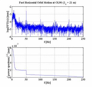
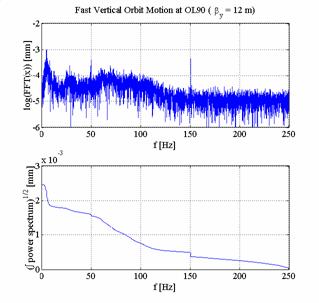
Figure 5: Power spectral density of horizontal and vertical orbit distortions and integrated power spectral density.
At first sight it may be sufficient to stabilize the beam position only at the insertion devices. Unfortunately this is not true. In addition it is necessary to control the orbit in the FODO arcs and in particular in the sextupoles. The orbit position in the sextupoles mainly determines the spurious vertical dispersion and so in turn the vertical emittance of the machine. Therefore the following layout of the feedback has been proposed. For fast orbit correction all position monitors are taken into account and all fast correctors in the new octant. Furthermore, two fast correctors per plane are installed at both ends of the damping wiggler section and one fast corrector is installed in each of the remaining straight sections. So, there are in total 41 fast horizontal and 41 fast vertical correctors planned in the scheme. The efficiency of this arrangement has been studied by simulations. A golden orbit has been determined as described in the closed orbit correction section. In addition the focusing strength of the quadrupoles has been randomly distorted to get a b-beating of approximately 20% in both planes. Then a 1µm misalignment was applied to all the quadrupole magnets of the PETRA III lattice. This orbit was then corrected with respect to the golden orbit. This procedure has been repeated 5000 times and the position at the insertion devices and the emittance in both planes have been recorded. The orbit at the insertion devices stays within the required limits. In Fig.6 recorded values of the emittance are shown. The figure shows that the fluctuations in the horizontal emittance are negligible and the fluctuations in the vertical emittance of approximately 8% stay within the tolerable limit. One should keep in mind that the simulation has been performed assuming rather pessimistic values for the RMS amplitude of the ground motion (1µm) and the b-beating (20 %). This shows that this correction scheme is robust.
Figure 6: Emittance distribution for successive fast orbit correction simulation of 5000 random sets.
In order to cover the required frequency range orbit information has to be taken at a rate of 4 kHz, which has been demonstrated to be feasible. The amplitudes of the correction kicks are small enough so that they can be supplied by air coil magnets similar to ESRF. The data transfer can be accomplished in ways that are used at ESRF and APS. For the time being we aim for a conventional system gathering all the information in a central unit to determine the kicks with an SVD algorithm and to use a PID controller. The orbit stabilization system is certainly demanding but it has been shown that such a system is feasible.
Home page of Orbit Movement and Beam Position Control