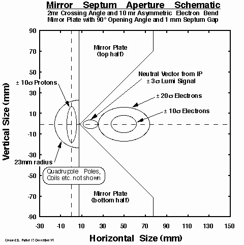
In response to the email message from Daniel Pitzl given below, I have tried to take the septum concept presented at a previous working group meeting a step further. As you may recall the idea was to very carefully cut away at the quadrupole mirror plate in such a way as to cause minimal field distortion. This was motivated by my observation that near the center of a quadrupole the magnitude of the field approaches zero, (unlike near the notch in a Lambertson magnet) so one might be able to find a good solution with a much thinner plate than that used in the present QS mirror quadrupole. This expectation was born out by field calculations done by Frau Marx. In these calculations a 1mm gap at the point of the "V" was found adequate to shape the field properly with very little field (less than 6 gauss) at the circulating e-beam position outside the mirror plate and still have an acceptable quadrupole field distribution for the circulating proton beam starting 1mm inside the mirror plate.
Inscribed Pole Radius  =    23.0           mm
   Total Coil Area     =   12,553       mm^2/pole
   Current Density     =   2.0922         A/mm^2
   Total Current       =    6.00          kA/pole
   Pole Tip Field      =    0.65         T (approx.)
     Gradient          =    28.2        T/m (approx.)
  Total Septum Angle   =    90.0            deg
  Magnetic Material    =   "Iron" (saturation, mu=>[6034.,1327.])
     Septum Gap        =     1.0             mm
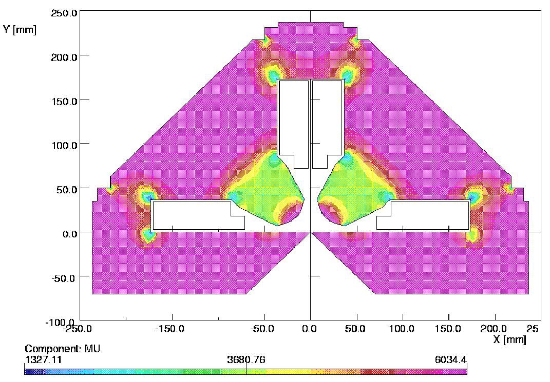
For an actual production magnet one would want to add a few millimeters of non-magnetic material in the neighborhood of the septum gap for structural (i.e. mechanical stability & assembly) reasons. Note that the choice of 23mm for the pole radius was motivated by the fact that a design file already existed for the new QZ magnet which has been made to implement the new HERA-B optics during the current winter shutdown. It was thus convenient for a scoping calculation to add a mirror plate to the geometry which Frau Marx had already created for me. For the present use as an IR magnet a slightly larger pole radius of about 30mm would be required. Fortunately there is virtually no saturation of the septum plate near the notch cutout and as long as one keeps the gradient constant this is likely to be true even for a larger pole radius (practical limit is to keep pole-tip field to about 0.8T).
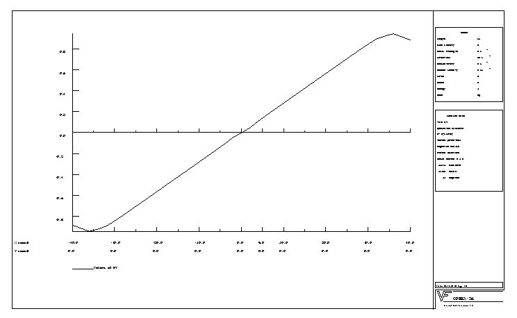
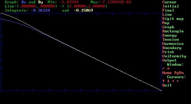
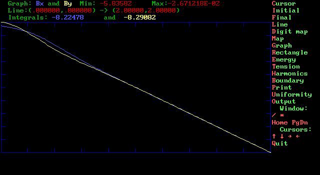
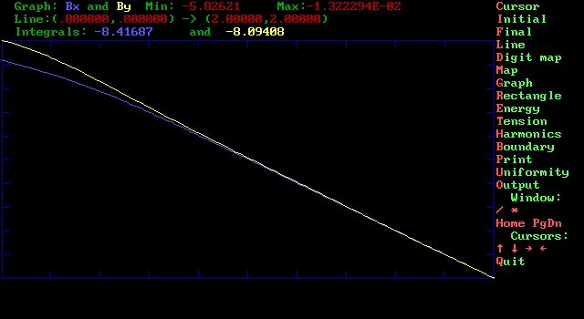
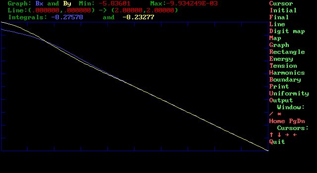
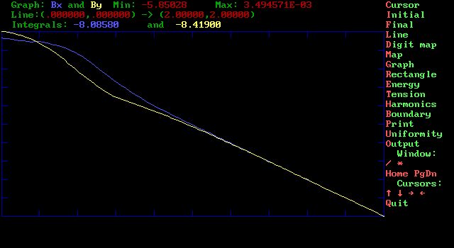
In the calculations which I have performed I have tried to create a gap of at least 10.mm total width (an order of magnitude larger than previous gap. The result for a simple knife edge cutoff, that the field is quite perturbed for about a half a gap width, 5.mm, from the origin should not be surprising. So the question is then: What sort of shaping should one give to the septum region notch in order to improve the field distribution seen by the proton beam? The viewgraphs given below illustrate my first attempt to answer this.
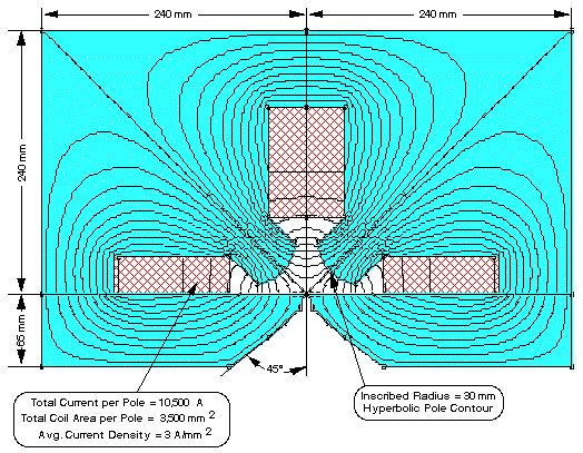
Inscribed Pole Radius  =    30.0         mm
   Total Coil Area     =   3,500.0    mm^2/pole
   Current Density     =     3.0        A/mm^2
   Total Current       =    10.5        kA/pole
   Pole Tip Field      =    0.85      T (approx.)
     Gradient          =    28.5      T/m (approx.)
  Total Septum Angle   =    90.0  deg (varies near tip)
  Magnetic Material    =   "Iron"  (constant mu = 6000.)
     Septum Gap        =     10.    mm (varies slightly)
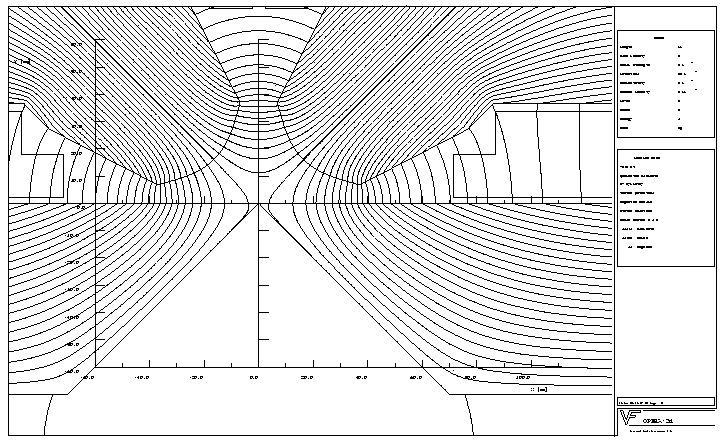
While the mesh used for these calculations has been made much richer nearer to the origin,
due to a hard limit in the code I have available to use, only 5000 mesh points are available
as compared to the sometimes more than 21k mesh Frau Marx uses in Opera/PE2D.
One half of the quadrupole is calculated and symmetry about
the mid plane (i.e. assume ideal fabrication & no systematic errors) is assumed.
I repeat, these are only intended as preliminary scoping calculations to get
an idea of what might be achieved by changing the geometry in the notch region
Not enough time was available for a systematic study including the influence of saturation of
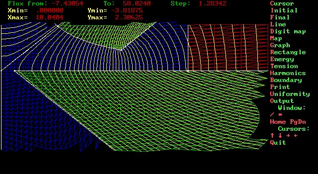
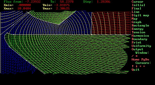
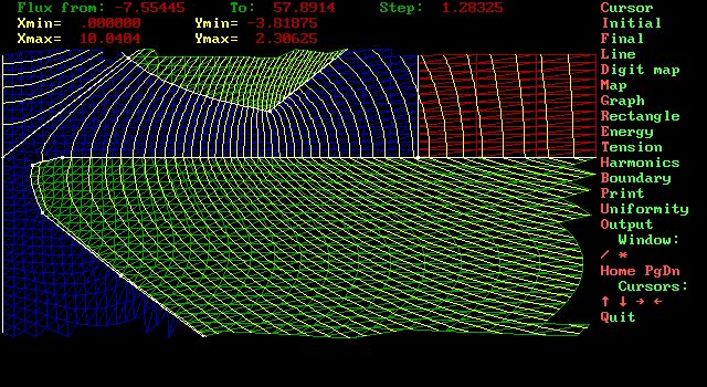
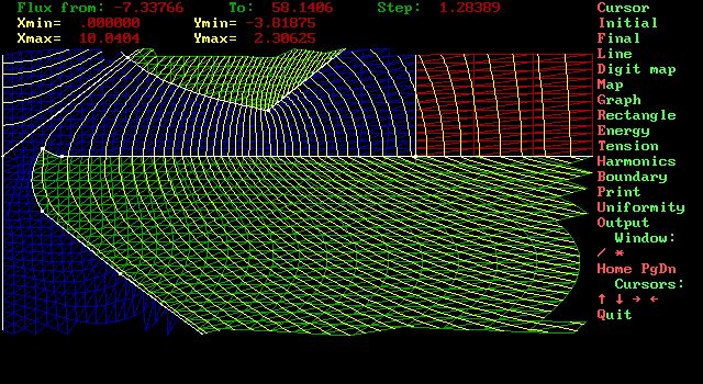
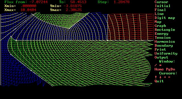
iron. Graphic outputs are saved in the form of jpeg files for www viewing. A generic overview of the geometry used in this study is given here [87k,JPG]. The horizontal extent of the main iron is 240 mm and the mirror plate is 65 mm at its thickest part. Note that for the 10mm gap considered, the physical opening available to pass a synchrotron radiation fan would be only 8mm after subtracting a 1mm thick vacuum chamber wall thickness on both sides.
Results for the various shapes are given here.
Dear colleagues,

in preparation of next weeks 'high lumi upgrade' meeting I would like
to announce some results from synchrotron radiation simulation.
Input is the 'Kose' e-beam optic with Ec=200keV.
I placed an absorber at 15m downstream, and a septum magnet also
at 15m. Head-on collisions.
The absorber albedo is 1.1% for coated Cu-Ag-W, and 3.3% for pure
copper (the present A24 is pure copper due to problems in coating a
tungsten absorber). The Cu spectrum is slightly harder: mean energy
backscattered of 124 keV vs. 105 keV for coated tungsten.

Shielding the central detector part (+- 1.2m around IP) is done
by C5 at z = -1.2m (vertical and inner horizontal jaw at 1.5 cm from
beams).
Secondary backscattering for photons from A15 is reduced by a C4
at z = +1.2m.
The radiation backscattered from the tip of the septum cannot be
shielded in this design, just from geometry.

Result (for coated tungsten A15):
  from A15: 7*10**8 gamma/s into central detector ( 70/BC)
  from Sep: 1*10**10 gamma/s into central detector ( 1000/BC)

It is debnatable, whether the rate from A15 can be tolerated.
However, the rate from the septum is excessive. I don't see a solution
in this design.

This is then the message: simple scaling of the present
collimator scheme does not work. More drastic modifications are
required, like the S-shape crossing (with or without crossing angle).
Perhaps we can identify a new 'preferred design' at the meeting.

See you next week,
                     Daniel Pitzl
�