|
HV 1- 20
HV 21 - 40
|
HV power supply distribution
for module 1-20 and 21-38. We have 40 HV channels but we need 76. Hence most of the HV channels are
multible occupied.

|
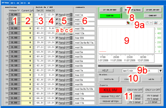
1
|
actual (measured) voltage
|
|
2
|
actual current. This field is getting red, if the current rises over the maximum allowed current. The threshold of this value can be set inside the settings file (see 10)
|
|
3
|
maximum Voltage. Can be set here (temporary) or in the settings file (see 10). This value will be reached after pressing LV ON, HV INIT (7) AND HV Ramp up/down (8) OR the RAMP button (5)
|
|
4
|
initial Voltage. Is used, when system is switching on (7) to set the SIPM into a defined state.
|
|
5a
|
marker: if this is set, the voltage will be ramped to (3), after pressing the LV ON, HV INIT (7)
|
|
5b
|
RAMP: the voltage will be ramped to (3), after pressing the RAMP button
|
|
5c
|
OFF: channel will go off immediately
|
|
5d
|
displays, if channel is on or in error state
|
|
6
|
comment line
|
|
7
|
HV ON/OFF area:
LV ON, HV INIT switches the +- 7V power sopplies on and the HV and ramps the HV up to the initial voltage level (4)
HV RAMP up/down: ramps the marked (5a) voltages to their given value (3)
LV OFF, HV OFF: all voltages (LV and HV) will be switched off
the two gree fields are indicating the two LV power supplies. In normal ON state, both must be green
|
|
8
|
CMB ON: switching all CMB’s on. After that they are going to be initialized.
CMB OFF: switch CMBs off
the two green fields are indicating the two +7V power supplies (+14V together). In normal state they shoud be green (ON)
|
|
9
|
display of the 20 currents (2).
|
|
9a
|
Zoom of x and y axis
|
|
9b
|
fast change of x and y axis
|
|
10
|
Settings file area:
SAVE to file: store the actual settings in a new file. A new header will be created. Comments inside a settings file shall start (as in C) with a “//”. If a file will be overwritten, the
existing comments will stay there. Only the 40 setting lines are going to be changed
LOAD from file: read a file and set the values into the control system
EDIT file: select a file and edit it with emacs
|
|
11
|
This area is for EXPERTS, or SHIFTIES to find out, why the system is not running.
KILL HV will switch of the HV immediately
the two recover buttons helps to recover from a trip.
all other buttons are for maintenance
|
|
|
|
|
Settings file
for loading different HV settings, the possibility of ASCII settin gs files are given. The location of these files is at: /home/pvss/projects/HCAL_CERN/scripts/settings or as link at: /home/caliceon/HCALsettings

|
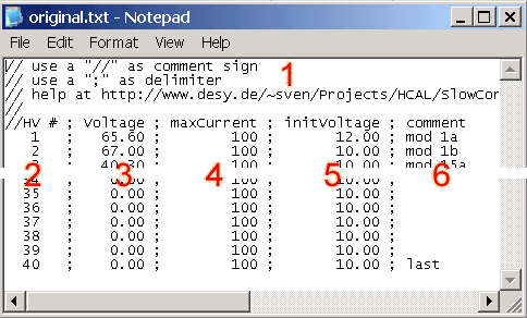
1
|
every file has a standard header with a comment area. A comment is starting with a “//”. The comment area can be changed at any time and as long as you want. After saving new settings in
an existing file, the old comments will NOT be overwritten.
The settings area will include the HV channels from 1 to 40. A double numbering is possible, but only the last value is been taken. A “;” has the delimiter function.
|
|
2
|
HV# from 1 to 40 represents the 40 high voltage channels
|
|
3
|
insert here the maximum voltage, which should be used
|
|
4
|
this field is only for display options. If the measured current rises above this value, the coresponding display field is blinking red
|
|
5
|
after switching on low voltage (LV) the HV will also switched on to this value
|
|
6
|
wrtie your comment into the last section
|
|
|

